How To Understand Wiring Diagrams
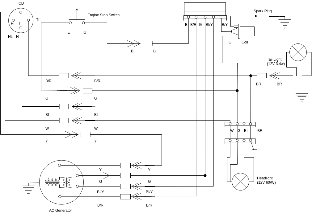
Wires or lines in circuit diagrams are usually horizontal or vertical. Code wire colour code wire colour b black p pink br brown r red g green sb sky blue gr gray si silver l blue v violet lg light green w white o orange y yellow if a cable has two colours, the first of the two colour code

Free Alarm Wiring Diagrams Wiring Tech
You have to know the difference between the lines in the drawing.

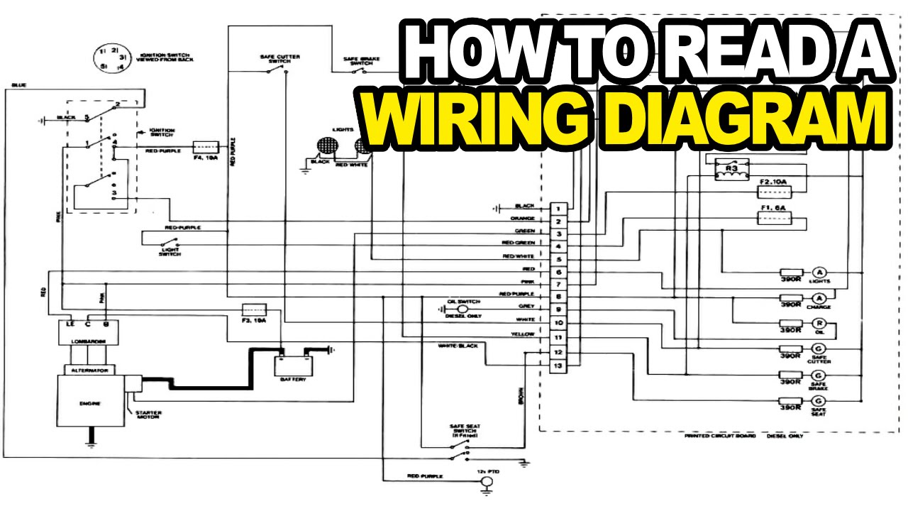
How to understand wiring diagrams. As you can see in the next figure the solid lines represent the. How to read the electrical wiring diagram: If playback doesn't begin shortly, try restarting your device.
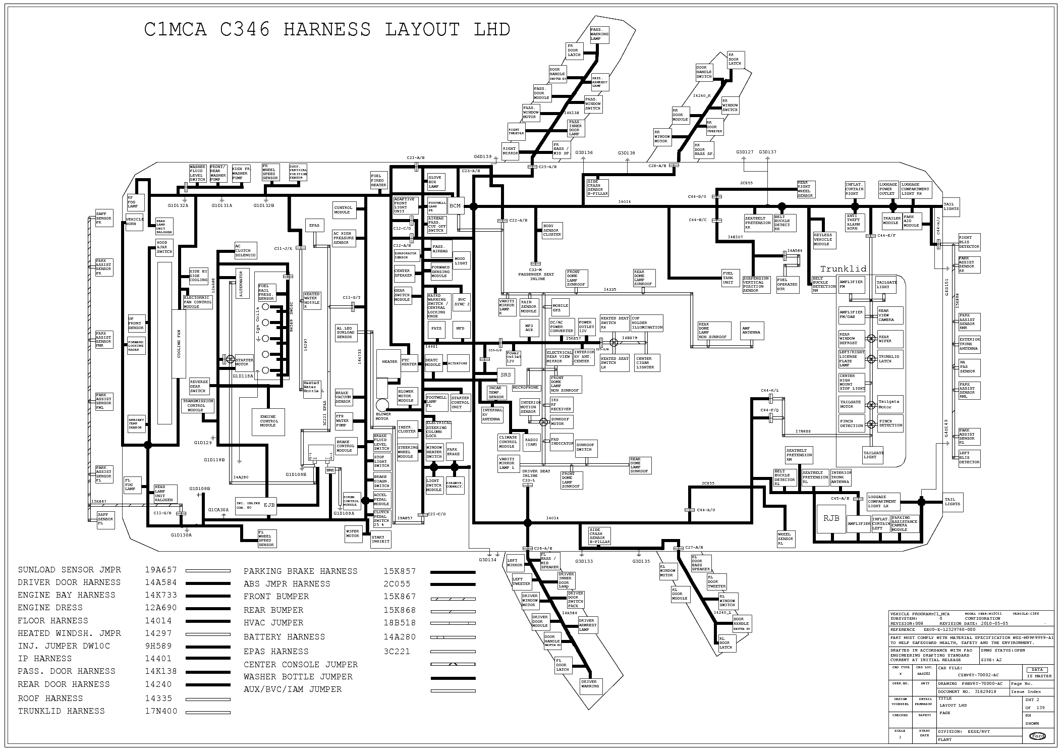
On very rare occasions a component may be placed at 45 degrees, but only for a very good reason. Wiring diagram may appear very complex when viewed as a whole, it can be simplified by breaking it down into smaller parts. Nets are represented as lines between component terminals.
Junctions and nodes wires can connect two terminals together, or they can connect dozens. Another feature they have in common are layers of detail. Control systems, for example, usually are designed so that an individual circuit controls only
This pictorial diagram shows us the physical links that are far easy to understand an electrical circuit or system. Notice that you might see some wiring diagrams are drawn with other directions but the common directions would still as we said before. Schematic nets tell you how components are wired together in a circuit.
It is also called an electrical circuit diagram. To begin understanding how to read and understand electrical circuit diagrams, take our basic circuit and draw it out as it would physically be wired. How to read electrical diagrams | wiring diagrams explained |.
We show our ac power source on the left with l1 and n coming out of it, our switch to the top, and our light to the left. A wiring diagram is a visual representation of components and wires related to an electrical connection. A wiring diagram shows all of the components and connecting points in their relative positions, and the conductors are shown following the routes that they take between them.
A wiring diagram is simply a pictorial representation of all the electrical connections in a specific circuit. These diagrams are an effective way of showing how wires are interconnected with different components in a system. How to read an electrical diagram lesson #1.
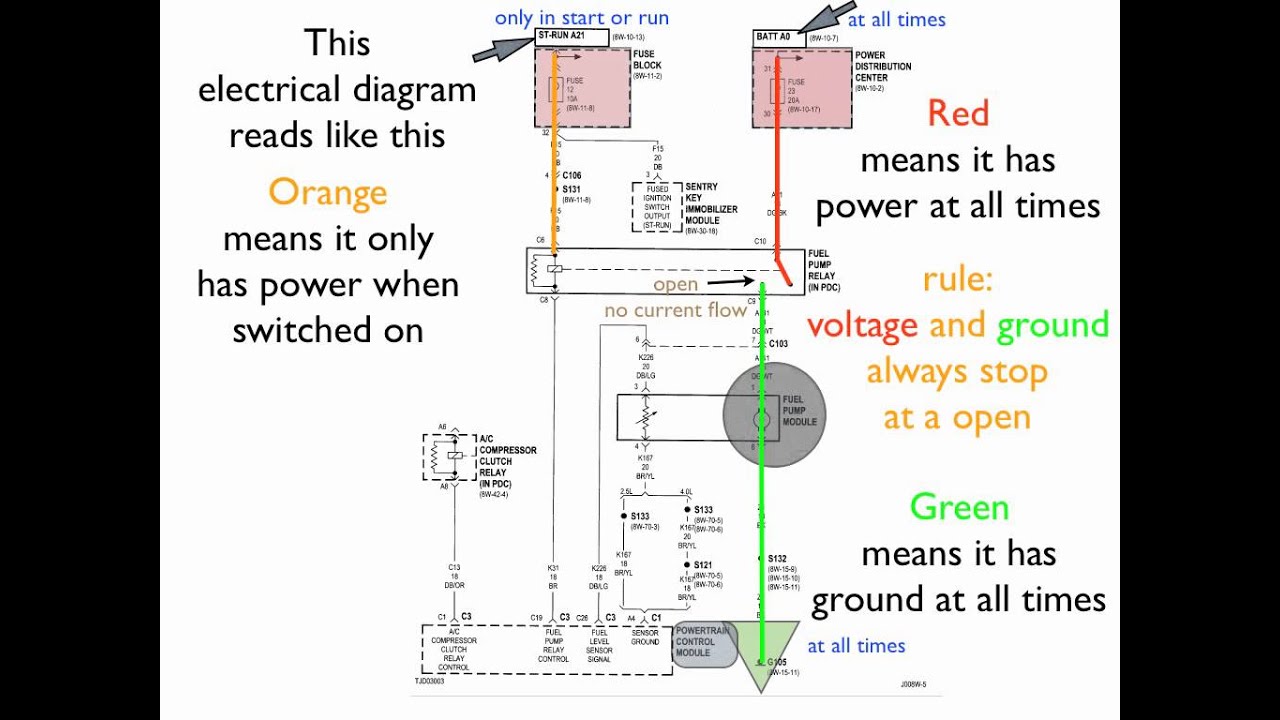
It shows how the electrical wires are interconnected and can also show where fixtures and components may be connected to the system. Wiring diagrams and road maps have much in common. Sometimes (but not always) they're a unique color, like the green lines in this schematic:
A wiring diagram is a simple visual representation of the physical connections and physical layout of an electrical system or circuit. A car wiring diagram can look intimidating, but once you understand a few basics you'll see they're actually very simple. Wire diagrams use wire color codes to identify the color of wire being used to connect different electrical components within the circuit.
One wiring diagram can signify all the interconnections, thereby signaling the relative locations. In electrical diagrams, every straight black line represents a wire. Www.handymanpf.complease help support this channel via paypal so i can continue to improve and make quality videos and make product reviews to help save you.
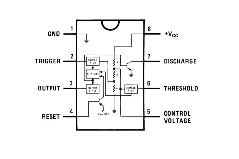
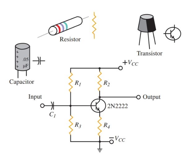
The wiring diagram shows different components in a circuit via different shapes and symbols. The common direction to draw a wiring diagram is from up to down and from left to right. All the electrical equipment will be identified with the sort of.
A car wiring diagram is a map. Use the legend to understand what each symbol on the circuit means. The two different diagrams are complimentary.
All wires are then identified using a color code and a number, but we'll see more about that later in this article. Some wire colors are specific to the wire's use such as black, white, red, and green, while others are used for component connection and change function from one circuit to another. Component symbols in a circuit diagram are usually placed horizontally or vertically.
On a diagram, there's no visual difference between wire gauges and materials. I was asked to help are newly trained technician who was perplexed by an odd fault. An electrical wiring diagram is nothing but a chat that represents the workflow of electrical equipment which are all involved in the system.
In some cases a diagonal line may be used which is placed at 45 degrees. To read it, identify the circuit in question and starting at its power source, follow it to the ground.

Dayton Thermostat Wiring Diagram at Wiring
electrical circuit diagram sample Wiring Diagram
Pioneer Car Stereo Speaker Wiring Diagram Wiring Sample
Wiring Diagram For Briggs And Stratton Ignition Wiring
How To Follow Electrical Schematics Wiring View And
Ford Focus Wiring Diagram Downloadactivetree

How To Wire A Relay Switch Diagram inspire referances 2022
How To Read Home Wiring Diagrams Home Wiring Diagram

DodgeRam2500WiringDiagram RAUR.US

electrical circuit diagram sample Wiring Diagram
How to Read an Electrical Wiring Diagram YouTube

Model A Ford Wiring Diagram Wiring Tech

Nest Thermostat E Wiring Diagram Uk at Wiring
Wiring Diagram For Briggs And Stratton Ignition Wiring

2005Cbr600rr Wiring Diagram Collection Wiring Diagrams
difference between electrical schematics and wiring
EzGoPdWiringDiagram RAUR.US

66 Mustang Ignition Switch Wiring Diagram at Wiring Diagram

24 Volt Trolling Motor Battery Wiring Diagram With Charger