Hvac Wiring Diagram Explained
I explain what each of the letter t. The first step in learning how to read any electrical wiring diagram is to learn what physical.
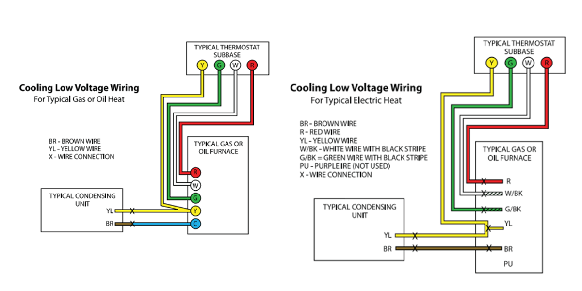
Hvac Low Voltage Wiring Furnace / Room thermostat wiring
Determine i (amps) = e (volts) / r (resistance in ohms) step 3.

Hvac wiring diagram explained. Ifany of the original wire,as supplied, must be replaced, use the same or equivalent type wire. C is known as the common terminal. It is the most common type of wiring diagrams.
Usually the electrical wiring diagram of any hvac equipment can be acquired from the manufacturer of this equipment who provides the electrical wiring diagram in the users manual see. The color of wire r is usually red and c is black. Heat pump thermostat wiring explained!
There are three basic types of circuit schematics used in hvac today. Thermostat wiring diagrams quality hvac guides 101 thermostat wiring diagrams quality hvac guides 101 This dictates the configuration of the wiring.
If you know a little bit about home heating and cooling systems, you probably realize that they are pretty complicated little systems! Thermostat wiring explained thermostat wiring hvac thermostat hvac. Two stage heat control wiring 7 this diagram is to be used as reference for the low voltage control wiring of your heating and ac system.
What you need to know. Check out multiple thermostat wiring diagrams as well as in depth video explanations on accurately wiring thermostats for various types of hvac systems! They are the line diagram, the ladder diagram, and the installation diagram.
David talks about basic compressor wiring. A wiring diagram is a simplified standard photographic depiction of an electrical circuit. These two connections will ensure that there is power to the thermostat that you are.
Wiring diagrams for hvac systems and other complicated electrical systems come in two. Your system likely only has one transformer, as most typical residential systems only use a single transformer for. Again referring to the honeywell thermostat ct31a1003 wiring diagram you can see it requires only two wires r and w.
Thermostat wiring explained intended for hvac thermostat wiring diagram by admin from the thousands of pictures on the net in relation to hvac thermostat wiring diagram, choices the top selections with greatest quality just for you, and now this images is usually among photos collections in this best pictures gallery concerning hvac thermostat wiring diagram. Notes some ac systems will have a blue wire with a pink stripe in place of the yellow or y wire. Determine power (watts) = amps x volts step 4.
Color of wire and termination. Use 60amp class k fuses only,. We offer simple explanations of how to.
Inside those compact units are electrical connections, fans, compressors, condensers, switches, coolants—the list goes on and on. Furthermore, this thermostat wiring diagram is specifically for a system with two transformers. Thermostat wiring diagrams quality hvac heat pump diagram explained wire a programmable chromalox how to construct 2003 silverado gm air conditioning.
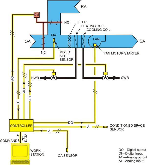
In the detailed design phase, the electrical designer must size and select the wires/cables, conduits, starters, disconnects and switchgear necessary for supplying power and control to hvac equipment. Schematic diagrams for hvac systems: And in article electrical wiring diagrams for air conditioning systems part one i explained the following points.
3 1 the ladder diagram. Always refer to your thermostat or equipment installation guides to verify proper wiring. In air condition systemcompressor is a main component to pump the refrigerant circulation in systemit like our heart to pump a blood all around human systemif this part breakdown or have a problemall system is paralyze.
You can think of these circuit schematics as road maps. Residential wiring diagrams and blueprints. To be wired inaccordance with n.e.c.and local codes.
How to read hvac wiring diagrams schematic and ladder diagrams. Use copper wire (75ºc min) only between disconnect switch and unit. As shown in the diagram, you will need to power up the thermostat and the 24v ac power is connected to the r and c terminals.
The coil absorbs heat from air passing over it. To keep track of wiring, hvac technicians rely on circuit schematics or visual representations of wiring programs. Always refer to your thermostat or equipment installation guides to verify proper wiring.
Colors, terminals, functions, voltage path! The condensing unit is like the evaporator coil but for an outdoor hvac unit. In this hvac installation training video, i show how to wire the low voltage thermostat wires into a furnace and ac unit.
That means there s no math. Unique trane heat pump thermostat wiring diagram thermostat wiring trane heat.

Thermostat Wiring Explained Thermostat wiring, Hvac

42 Honeywell Ra832a Wiring Diagram Wiring Diagram Source

19 Images Hvac Capacitor Wiring Diagram
21 Elegant Understanding Hvac Wiring Diagrams Pdf


Thermostat wiring, Hvac thermostat, Hvac

Hvac Thermostat Wiring Diagram — UNTPIKAPPS
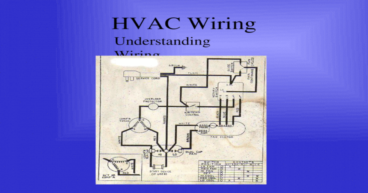
HVAC Wiring Understanding Wiring. HVAC Wiring Wiring
Wiring And Fuse Image All Free Accessed Wiring Databse


Pin by jaa624 on good2Know Electrical wiring diagram
Hvac Systems new Hvac System Diagram
Hvac Systems new Schematic Diagram Of Hvac System

![]()
Hvac Thermostat Wiring Voltage Wiring Diagram

Hvac Wiring Diagrams 101 Thermostat Wiring Diagrams Wire

Boiler Thermostat Wiring Gas Fired Furnace Wiring

Wiring Diagram Home. Wiring Diagram Home. Wiring Diagram

HVAC Wiring Understanding Wiring. HVAC Wiring Wiring
Hvac System Hvac System Explained

Hvac Blower Motor Wiring Diagram

House Thermostat Wiring Diagrams Air Conditioning